AM Transmitter & Superheterodyne Receiver
A MOSFET AM modulator and a 455 kHz IF receiver, designed and simulated in Proteus.
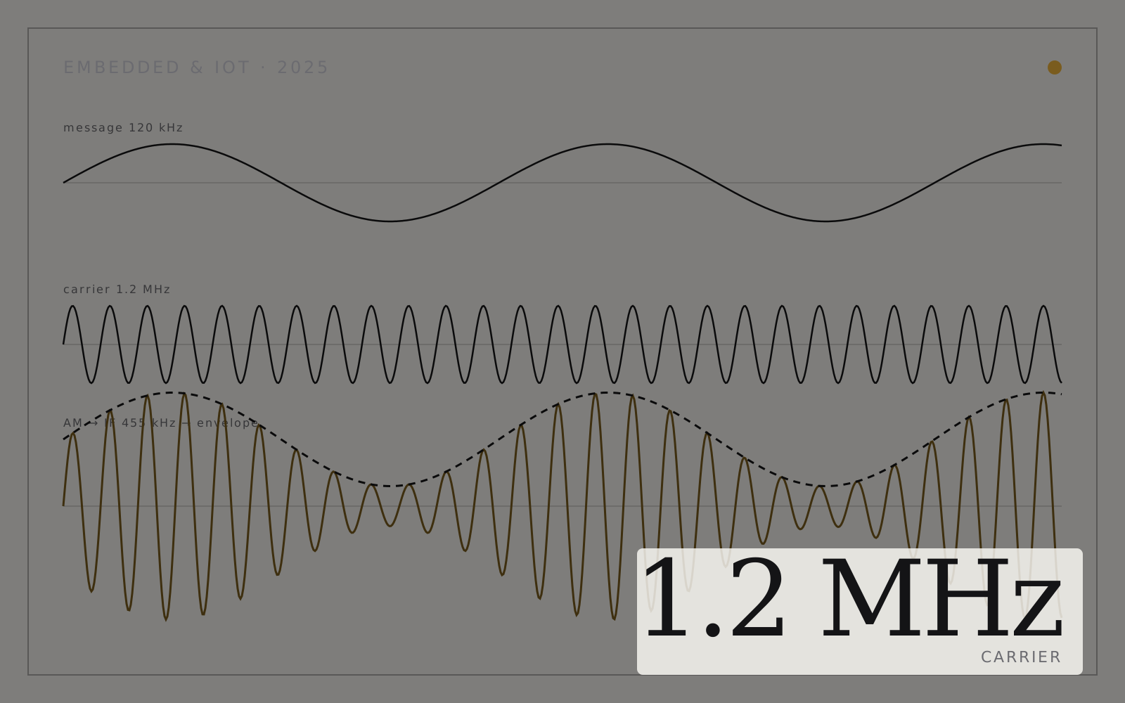
A medium-wave communication chain: a 1.2 MHz carrier modulated by a MOSFET stage, then a superheterodyne receiver that mixes down to a 455 kHz intermediate frequency and recovers the audio with an envelope detector. Every stage is verified on the Proteus oscilloscope.
README · rendered from GitHub
AM Modulator and Superheterodyne AM Receiver





Overview
This project implements an Amplitude Modulation (AM) transmitter and a corresponding Superheterodyne AM receiver for the medium-wave (MW) band (535 kHz – 1605 kHz). The entire design and testing were performed in Proteus 8, using discrete electronic components (resistors, capacitors, inductors, diodes, MOSFETs) and frequency down-conversion to 455 kHz IF, and signal recovery via envelope detection.
Objective
- Design a MOSFET‑based AM transmitter that modulates a 120 kHz message onto a 1.2 MHz carrier.
- Build a Superheterodyne receiver that down‑converts the incoming 1.2 MHz AM signal to a 455 kHz IF, then recovers the original audio via an envelope detector.
- Verify and visualize each stage—message, carrier, modulated RF, IF, and demodulated output—using Proteus’s oscilloscope.
Key Components & Circuit Design
AM Transmitter
- Carrier Frequency: 1.2 MHz (displayed at 12 MHz in Proteus for clearer oscilloscope traces)
- Message Signal: 120 kHz sine wave from VSM Signal Generator
- Modulator Topology: Common‑source MOSFET (2N7000) with passive bias network
- Gate bias network: 10 kΩ & 100 kΩ resistors
- RF coupling capacitor: 0.01 µF (gate to carrier source)
- Drain resistor: 4.7 kΩ
- RF Amplifier Stage:
- LC tank tuned to 1.2 MHz (L = 10 µH, C = 100 pF)
- Common‑source MOSFET amplifier for post‑modulation gain
Superheterodyne Receiver
- RF Front End
- Band‑pass LC filter centered at 1.2 MHz (L = 10 µH, C = 120 pF)
- Low-noise MOSFET amplifier for initial RF gain
- Mixer / Frequency Converter
- Local Oscillator: 1.655 MHz (to mix 1.2 MHz → 455 kHz IF)
- Mixer implemented with a diode ring (or single‑balanced MOSFET mixer)
- Output filtered to isolate 455 kHz IF
- IF Amplifier
- Tuned LC amplifier at 455 kHz (L = 100 µH, C = 1000 pF) for selectivity and gain
- Envelope Detector
- Diode (1N4148) + RC network (R = 10 kΩ, C = 0.1 µF)
- Recovers the 120 kHz message envelope → baseband audio
- Complete Circuit
Simulation Environment
- Tool: Proteus 8 (Version 8.x or higher)
- Key Instruments: Virtual Signal Generator (VSM), Virtual Oscilloscope
- Carrier Display Workaround: Proteus oscilloscope struggled to show a clean 1.2 MHz trace, so all “carrier” screenshots were taken at 12 MHz, though component values are calculated for 1.2 MHz.
Results (Oscilloscope Captures)
| Stage | Frequency Shown | Observations |
|---|---|---|
| Message Input | 120 kHz | Clean sine wave from VSM generator |
| Carrier (displayed) | 12 MHz | Stable sinusoid (actual tuned to 1.2 MHz) |
| AM Modulated Output | 12 MHz | Envelope follows 120 kHz message |
| IF Signal After Mixer | 455 kHz | Clean IF sine wave, ready for IF amplifier |
| Demodulated Audio | 120 kHz (envelope) | Recovered baseband envelope after RC filter |
- Modulation Depth: Approximately 80 – 90%
- IF Selectivity: Good rejection of unwanted mixer products
- Audio Recovery: Envelope detector output matches original 120 kHz message envelope
More in Embedded
Related projects
 Embedded2025
FreeRTOS Smart Energy Monitor
STM32F746 tasks compute Vrms, Irms and kWh; an ESP32 pushes it to a cloud dashboard.
- STM32F746
- FreeRTOS
- ESP32
- C/C++
 Embedded2024
Crowd-Sourced AQI Monitor
Six sensors, Bluetooth to a phone app, and AQI within 1% of the US Embassy station.
- Arduino UNO
- C/C++
- PMS5003
- MQ-series
 Embedded2024
Fully Automated Egg Incubator
ATmega328P climate control and egg turning that hatched every pigeon egg in 18 days.
- ATmega328P
- Arduino IDE
- Atmel Studio
- Proteus