Line-Following Robot
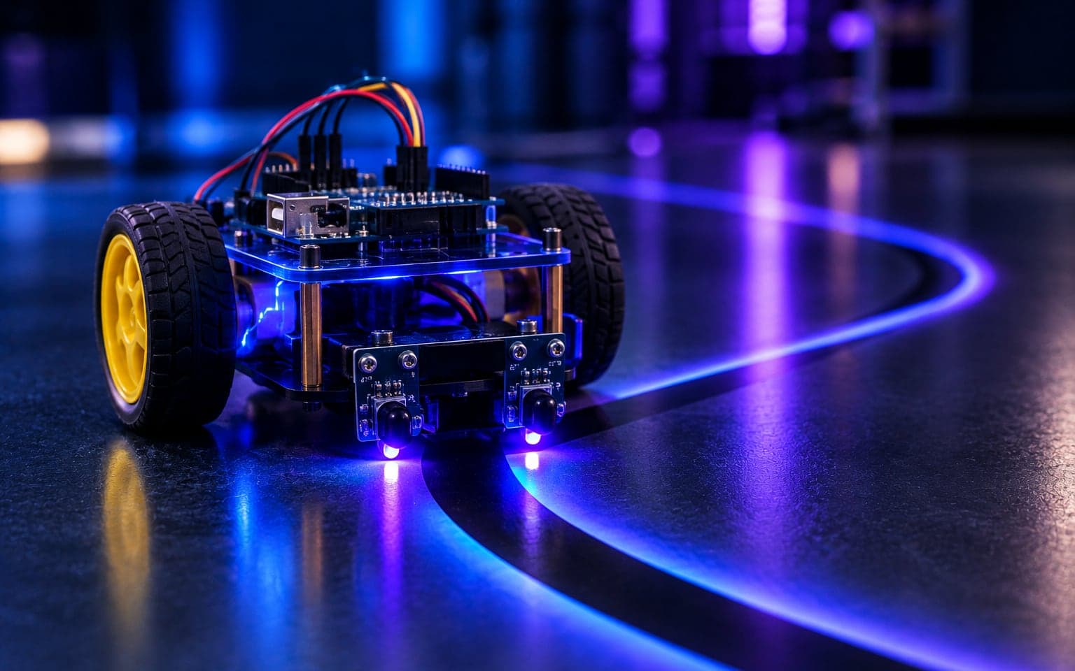
Two IR sensors and a decision loop keep the car on a black line.
A classic line follower on Arduino UNO with dual infrared sensors and real-time direction control, demonstrating sensor integration and closed-loop decision making.
README · rendered from GitHub
Line Following Robot






Overview / Introduction
This project demonstrates a line-following robot built using an Arduino UNO and two infrared (IR) sensors. The robot detects the path (usually black line on a white surface) and follows it using logic-based decision-making. It controls two motors through a motor driver module and uses IR sensors to detect the black or white surface below.
Features
- Follows a predefined black line on a white surface
- Real-time direction control using dual IR sensors
- Smart turn left/right or stop based on IR feedback
- Customizable speed settings for forward and turn
- Simple logic and easy-to-understand code
Hardware Components
- Arduino UNO (1x)
- IR Sensor Modules (2x)
- L298N Motor Driver (1x)
- DC Motors (4x)
- Robot Chassis (1x)
- Wheels (4x)
- Jumper Wires
- Battery Pack (1x)
IR Sensors (Infrared Sensors)
Infrared (IR) sensors are the primary components used for line detection in this robot. Each IR sensor module consists of:
- IR LED (Emitter) — Emits infrared light onto the surface.
- Photodiode/Phototransistor (Receiver) — Detects the reflected IR light.
Working Principle:
- White surface reflects IR light → Photodiode detects it → Output is LOW
- Black line absorbs IR light → Photodiode detects nothing → Output is HIGH
- This difference in reflection allows the robot to detect where the black line is and respond accordingly.
- If both sensors see white → go forward.
- If left sees white and right sees black → turn left.
- If right sees white and left sees black → turn right.
- If both see black → stop.
L298N Motor Driver
The L298N Motor Driver Module is used to control the two DC motors of the robot. It acts as an interface between the low-power Arduino and the high-power motors.
Features:
- Can control the direction and speed of two DC motors.
- Accepts PWM (Pulse Width Modulation) signals from Arduino to adjust motor speed.
- Has two enable pins (ENA, ENB) and four control pins (IN1, IN2, IN3, IN4) connected to the Arduino.
Working:
- ENA / ENB: Used to control the speed of motors via
analogWrite(). - IN1/IN2 (for Motor A) and IN3/IN4 (for Motor B): Used to control motor direction via
digitalWrite().
Example:
digitalWrite(IN1, HIGH); digitalWrite(IN2, LOW);
How to Charge Lithium-Ion
What You Need:
- TP4056 charging module (with or without protection circuit)
- Lithium-Ion battery (typically 3.7V, like an 18650 cell)
- Power source (5V via USB cable or 5V adapter)
Wiring Connections
| TP4056 Pin | Connects To | Description |
|---|---|---|
| BAT+ | Battery Positive (+) | Connect to battery's positive terminal |
| BAT- | Battery Negative (–) | Connect to battery's negative terminal |
| IN+ | 5V Power Positive | USB VCC or 5V adapter |
| IN- | 5V Power Ground | USB GND or adapter GND |
| OUT+ | Output Positive (Optional) | Same as BAT+ if present |
| OUT- | Output Negative (Optional) | Same as BAT– if present |
Charging Status (LED Indicators)
- 🔴 Red LED ON → Charging
- 🟢 Blue/Green LED ON → Fully Charged (approx. 4.2V)
TP4056 Specifications
- Input Voltage: 4.5V – 5.5V (recommended: 5V)
- Charging Cut-off Voltage: 4.2V
- Max Charging Current: 1A (default, adjustable by changing onboard resistor)
Charging Steps
- Connect BAT+ and BAT- to the Lithium-ion battery terminals.
- Connect IN+ and IN- to a 5V power supply (USB or adapter).
- Observe LED indicators:
- Red = Charging
- Green/Blue = Fully Charged
- Disconnect power once fully charged (unless using protected module).
Safety Tips
- Never leave charging unattended.
- Use only genuine 3.7V Li-ion batteries.
- Avoid short circuits on BAT terminals.
- Do not reverse polarity — it can damage the module and the battery.
- Use TP4056 with protection for safer charging and discharging.
Software Requirements
- Arduino IDE
- USB drivers for Arduino
- Serial Monitor (for debugging)
Pin Configuration
| Component | Arduino Pin |
|---|---|
| IR Left Sensor | A1 |
| IR Right Sensor | A0 |
| Motor Left Enable | 5 (ENA) |
| Motor Right Enable | 3 (ENB) |
| Motor Left Pin 1 | 11 |
| Motor Left Pin 2 | 10 |
| Motor Right Pin 1 | 9 |
| Motor Right Pin 2 | 8 |
Decision Making Logic
The robot makes decisions based on the IR sensor input:
- Both sensors LOW → Move Forward
- Left LOW, Right HIGH → Turn Left
- Left HIGH, Right LOW → Turn Right
- Both HIGH → Stop
Function Descriptions
moveForward()— Moves robot forward by setting both motors in forward direction.turnLeft()— Rotates robot left by reversing the right motor and driving the left forward.turnRight()— Rotates robot right by reversing the left motor and driving the right forward.stopMotors()— Stops both motors immediately.
Circuit Diagram
How to Run
- Assemble all components as per the wiring table.
- Open the Arduino IDE and upload the provided code.
- Place your robot on a track with a black line on a white surface.
- Power the robot and watch it follow the line.
- Adjust motor speeds if needed in
Forward_SpeedandTurn_Speed.
Demonstration
Applications
- Entry-level robotics and automation
- Educational STEM learning kits
- Industrial line-following transport bots
- Maze-solving robots (with enhancements)
Future Improvements
➕ Add PID Control to reduce overshooting and create smoother navigation. ➕ Introduce EEPROM-based line calibration for better performance. ➕ Add a camera module and evolve toward vision-based line following.
Troubleshooting / Common Issues
- Robot not moving: Check motor wiring and power supply.
- Incorrect turns: Swap motor direction pins if needed.
- Sensors not detecting line: Ensure correct surface contrast and proper IR sensor height.
- Random behavior: Use Serial Monitor to debug sensor readings.
Credits / Acknowledgements
Developed by Awais Asghar as part of hands-on robotics projects.
License
This project is released under the MIT License. Feel free to use, modify, and share it with credit.
More in Robotics
Related projects
 Robotics2024
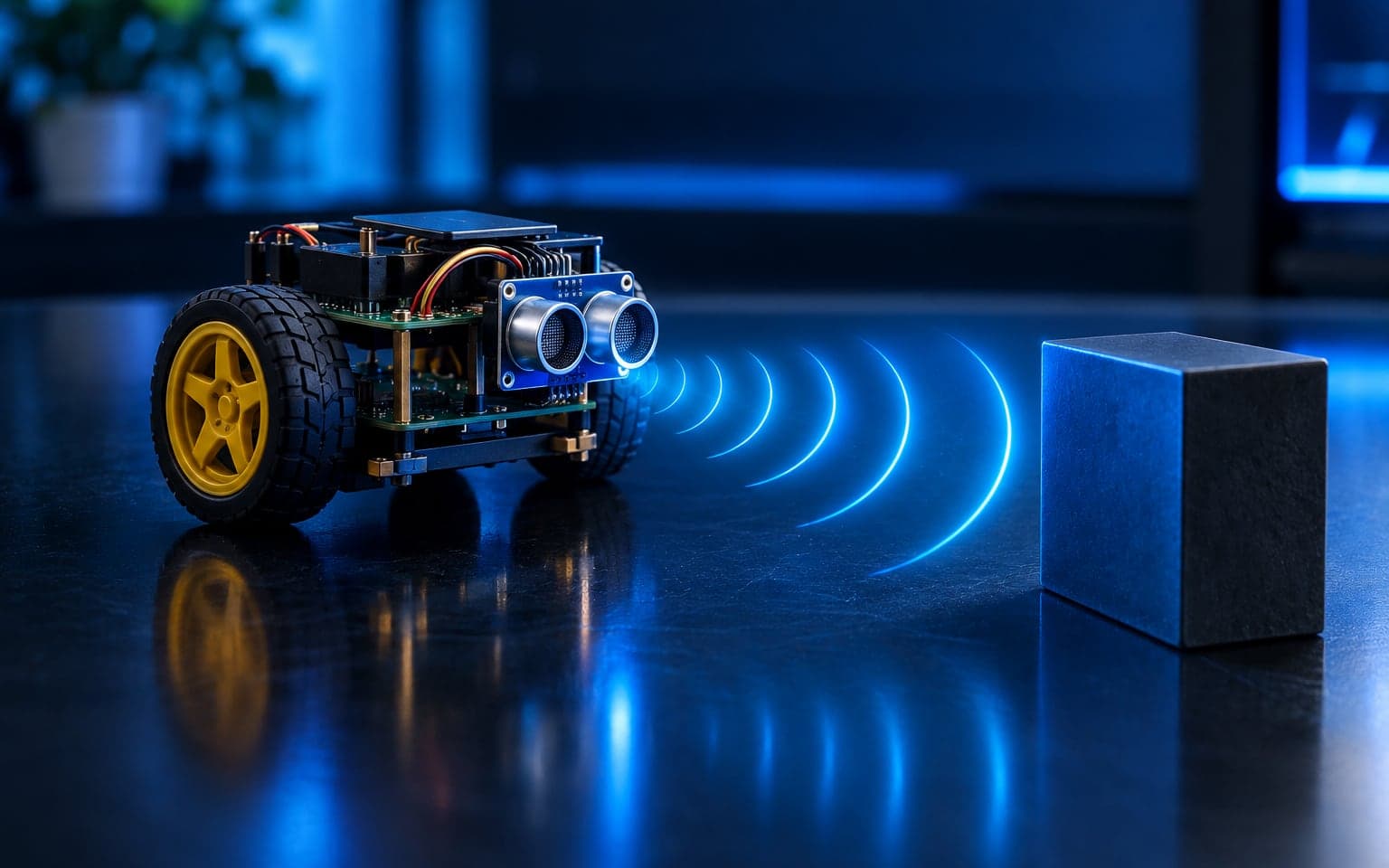
Obstacle-Avoiding Robot
An ultrasonic rover that stops, reverses and turns around anything in its way.
- Arduino UNO
- C/C++
- HC-SR04
- L298N
 Robotics2024
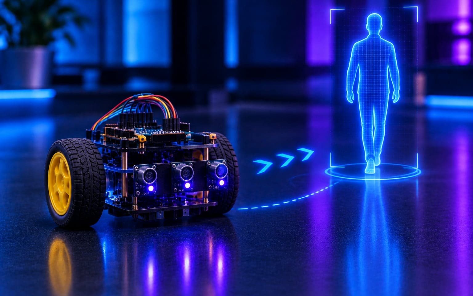
Human-Following Robot
A compact robot that tracks and follows a person with three IR sensors.
- Arduino UNO
- C/C++
- IR sensors