Obstacle-Avoiding Robot
An ultrasonic rover that stops, reverses and turns around anything in its way.
An Arduino robot with an ultrasonic range finder and motor driver that navigates autonomously by detecting obstacles within a set distance and re-planning its heading.
README · rendered from GitHub
Obstacle-Avoiding Robot






Introduction
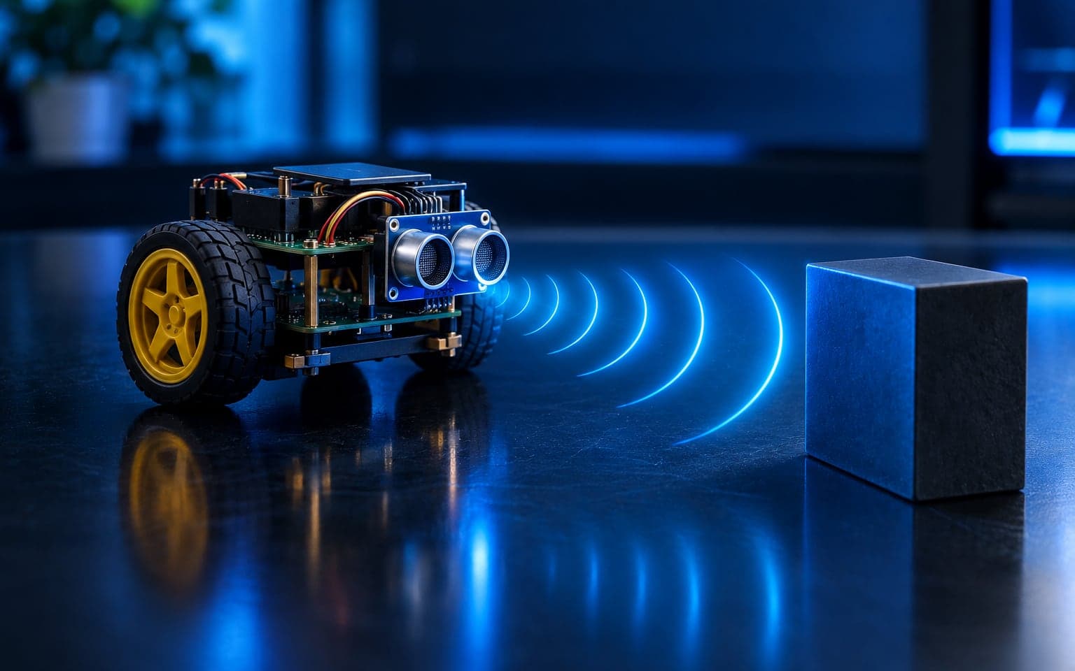
This project involves designing an autonomous robot that avoids obstacles using an ultrasonic sensor. The robot moves forward freely until it detects an obstacle within a predefined distance, upon which it stops, moves backward, and turns left to find a new path.
Features
- Real-time obstacle detection
- Automatic decision-making for navigation
- Autonomous movement using DC motors
- Efficient obstacle-avoidance logic
- Simple and cost-effective design
Hardware Components
- Arduino Uno (1x)
- Ultrasonic Sensor HC-SR04 (1x)
- L298N Motor Driver Module (1x)
- DC Geared Motors (4x)
- Robot Chassis (1x)
- Wheels (4x)
- Jumper Wires
- Power Supply (Battery)
Pin Configuration
| Component | Arduino Pin |
|---|---|
| Ultrasonic Sensor Trig | 2 |
| Ultrasonic Sensor Echo | 3 |
| Motor Driver ENA | 11 |
| Motor Driver ENB | 10 |
| Left Motor Pin 1 | 7 |
| Left Motor Pin 2 | 6 |
| Right Motor Pin 1 | 5 |
| Right Motor Pin 2 | 4 |
Functional Overview
Ultrasonic Sensor
- Measures the distance to the nearest object using sound waves.
- The trigger pin sends a short pulse, and the echo pin receives the reflected pulse.
- The time taken for the pulse to return is converted to distance.
Motor Control
- The L298N motor driver controls the left and right DC motors.
- Motors are driven in different directions to achieve forward, backward, or turning movements.
- Output A, Output B - To connect two motors.
- Driver Power Input - Board can accept 5V to 35V which will act as the power supply to motor and internal 5V voltage regulator (if it is enabled using jumper).
- GND - Common Ground
- 5V Output / Logic Input Voltage - This pin will give 5V output if the on-board regulator is enabled using the jumper, other we should give the logic supply (5V in the case of Arduino Uno) to this pin.
- IN1, IN2, IN3, IN4 - H-Bridge control inputs which can be used to control direction of motors.
- Enable A and Enable B pins are used for enabling each bridge or for controlling the speed of the motors using PWM.
Movement Logic
moveForward(): If no obstacle is detected within 15 cm then sets motor directions and speeds for forward motion.moveBackward(): Reverses the motors direction for 2.5 seconds upon obstacle detection.turnLeft(): Rotate the robot left for 2 seconds to find a clear path by controlling motor directions and speeds.Stop(): When an obstacle is detected it stops the robot by setting motor speeds to zero.
How to Charge Lithium-Ion
What You Need:
- TP4056 charging module (with or without protection circuit)
- Lithium-Ion battery (typically 3.7V, like an 18650 cell)
- Power source (5V via USB cable or 5V adapter)
Wiring Connections
| TP4056 Pin | Connects To | Description |
|---|---|---|
| BAT+ | Battery Positive (+) | Connect to battery's positive terminal |
| BAT- | Battery Negative (–) | Connect to battery's negative terminal |
| IN+ | 5V Power Positive | USB VCC or 5V adapter |
| IN- | 5V Power Ground | USB GND or adapter GND |
| OUT+ | Output Positive (Optional) | Same as BAT+ if present |
| OUT- | Output Negative (Optional) | Same as BAT– if present |
Charging Status (LED Indicators)
- 🔴 Red LED ON → Charging
- 🟢 Blue/Green LED ON → Fully Charged (approx. 4.2V)
TP4056 Specifications
- Input Voltage: 4.5V – 5.5V (recommended: 5V)
- Charging Cut-off Voltage: 4.2V
- Max Charging Current: 1A (default, adjustable by changing onboard resistor)
Charging Steps
- Connect BAT+ and BAT- to the Lithium-ion battery terminals.
- Connect IN+ and IN- to a 5V power supply (USB or adapter).
- Observe LED indicators:
- Red = Charging
- Green/Blue = Fully Charged
- Disconnect power once fully charged (unless using protected module).
Safety Tips
- Never leave charging unattended.
- Use only genuine 3.7V Li-ion batteries.
- Avoid short circuits on BAT terminals.
- Do not reverse polarity — it can damage the module and the battery.
- Use TP4056 with protection for safer charging and discharging.
Software Requirements
- Arduino IDE
- Arduino USB Drivers
- Serial Monitor for debugging
Working Principle
The ultrasonic sensor emits sound waves and calculates the distance based on the time taken by the echo. If the detected distance is greater than 15 cm, the robot moves forward. If it's less than 15 cm, the robot stops, moves backward for a short duration, and then turns left to avoid the obstacle.
How to Run
- Connect all hardware components as per the circuit diagram.
- Open the Arduino IDE.
- Paste the provided code into a new sketch.
- Select the correct board (Arduino Uno) and port.
- Upload the code.
- Place the robot on the floor and power it on.
- Watch it autonomously navigate around obstacles.
Demonstration
Applications
- Smart autonomous vehicles
- Line follower upgrades
- AI navigation-based robots
- Industrial automation robots
- Educational STEM kits
Future Improvements
- Add a PID control
- Implement object mapping using SLAM
Troubleshooting / Common Issues
- Robot not moving: Check motor connections and power supply.
- Ultrasonic sensor not detecting: Ensure correct wiring of
trigandechopins. - Inconsistent movements: Confirm proper voltage to the motor driver.
- Serial Monitor not showing: Make sure the correct baud rate (9600) is selected.
Credits / Acknowledgements
This project was created and implemented by Awais Asghar as a part of learning embedded systems and robotics using Arduino.
License
This project is licensed under the MIT License. You are free to use, modify, and distribute it with attribution.
More in Robotics
Related projects
- Arduino UNO
- C/C++
- IR sensors
 Robotics2024
Human-Following Robot
A compact robot that tracks and follows a person with three IR sensors.
- Arduino UNO
- C/C++
- IR sensors